I don’t use CAD professionally, and it had been over 20 years since I last used it. I wanted a headphone stand that did more than hold headphones, I wanted built-in compartments for my glasses, a notebook, and the small stuff that clutters a desk. Nothing on the market fit the exact footprint and layout I had in my head, so I decided to design it myself, with an AI doing the heavy CAD lifting while I directed the design.
Here’s how it actually went, mistakes included.
Step 1: Sketch it on paper first
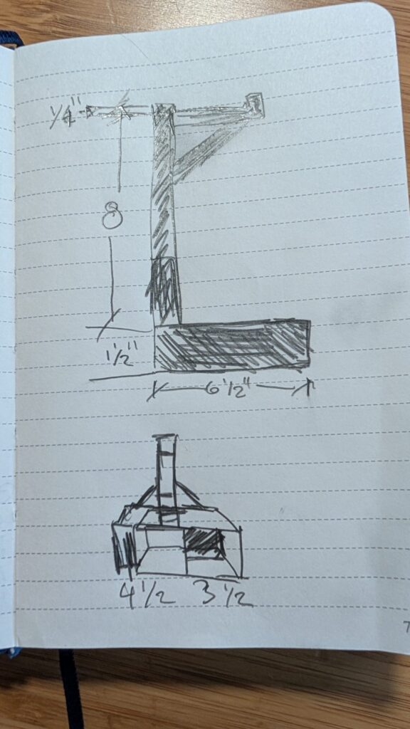
Before touching any software, I drew the design by hand on sticky notes, front view, left side, right side, each labeled. This mattered more than I expected. Having three angles on paper forced me to actually think through the geometry (compartment splits, post height, arm angle) before generating a single line of code.
Dimensions I started with:
- Base: 8″ wide x 6.5″ deep x 1.5″ tall
- Left compartment: 4.5″ wide, closed box
- Right side: split into two compartments (front-opening and right-opening)
- Center back post: 0.75″ x 0.75″ x 8.25″ tall
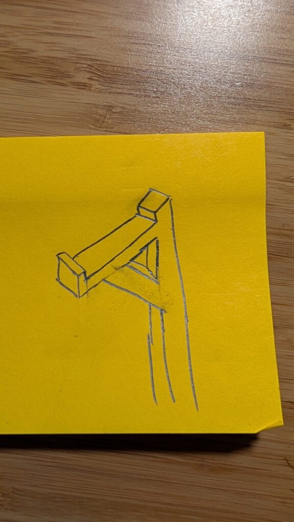
- Headphone arm: 0.75″ x 0.75″, extending 2.5″ forward, sitting 0.25″ below the post’s top
- 45-degree support braces connecting the post to the base and to the arm
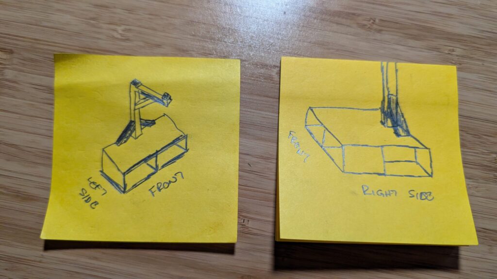
Step 2: Turn sketches into parametric CAD
I initially tried FreeCAD directly, but for a design this dimension-heavy, it was faster to have Claude write the geometry as code (using a Python CAD library called CadQuery) rather than clicking through a GUI. Every dimension became a variable, so changing “4.5 inches” to something else later would just mean editing one number, not rebuilding geometry by hand.
Prompt I used to kick it off:
“I want to create a design to hold my headphones with some compartments underneath… Before you do any work, would it be easier for you to do it, and help me create the file to view in FreeCAD? Then I can review it, make changes, and then save and add to Bambu studio to 3D Print?”
Claude generated the first pass, rendered a preview image so I could sanity-check it before committing to anything, and exported both STEP (fully editable) and STL (for printing) files.
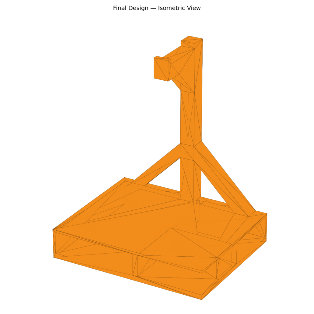
Step 3: The unglamorous part, catching what the render got wrong
This is the part most tutorials skip. The first version had real problems:
- A compartment wall was missing entirely (two “separate” bins had silently merged into one open cavity)
- Support braces that were supposed to be true 45-degree angles were actually closer to flat
- The braces meant to support the post weren’t actually touching it, there was a visible structural gap
Every fix followed the same loop: describe what’s wrong → get a new render → check it against the actual numbers, not just the picture (a couple of early renders looked ambiguous due to rendering artifacts, so we cross-checked bounding-box coordinates directly to confirm alignment rather than trusting a picture alone). It took several rounds. That’s normal. CAD is unforgiving of vague instructions, and being specific (“the joists need to align with the back of the post, not the centerline”) mattered more than being polite about it.
Step 4: Prepping for a print that won’t fail
Two decisions mattered here:
Orientation. Printing the model upright (post standing vertical) would have meant the entire arm and post structure floating in mid-air, needing heavy supports and risking a failed print. Instead, we rotated the whole model so the flat back face sits on the print bed, laying the post down flat. That turned a cantilevered nightmare into an almost fully self-supporting print.
Units. This one nearly ruined the file. The model was built using raw inch values (8, 6.5, 1.5, etc.), but STL files carry no unit information, they’re just numbers, and Bambu Studio always reads those numbers as millimeters. Left uncorrected, an “8 inch wide” stand would have printed 8 millimeters wide, about the size of a fingernail. Catching that before slicing saved a wasted print.
Step 5: Slicing and printing in Bambu Studio
A few real hiccups on the way to a successful print:
- A “floating cantilever” warning on the small lip at the arm’s tip, fixed by switching to tree supports and disabling “support on build plate only”
- A nozzle mismatch error (the slicer profile was set for a 0.2mm nozzle, the printer actually had a 0.4mm nozzle installed), fixed by updating the nozzle diameter setting so Bambu Studio offered the correct profile list
- A printer-binding issue in Bambu Studio’s Device tab that had nothing to do with the model itself, just needed the printer paired via PIN code
None of these were CAD problems. They were print-pipeline problems, and worth knowing about if you’ve never taken a model from slicer to printer before.
The result
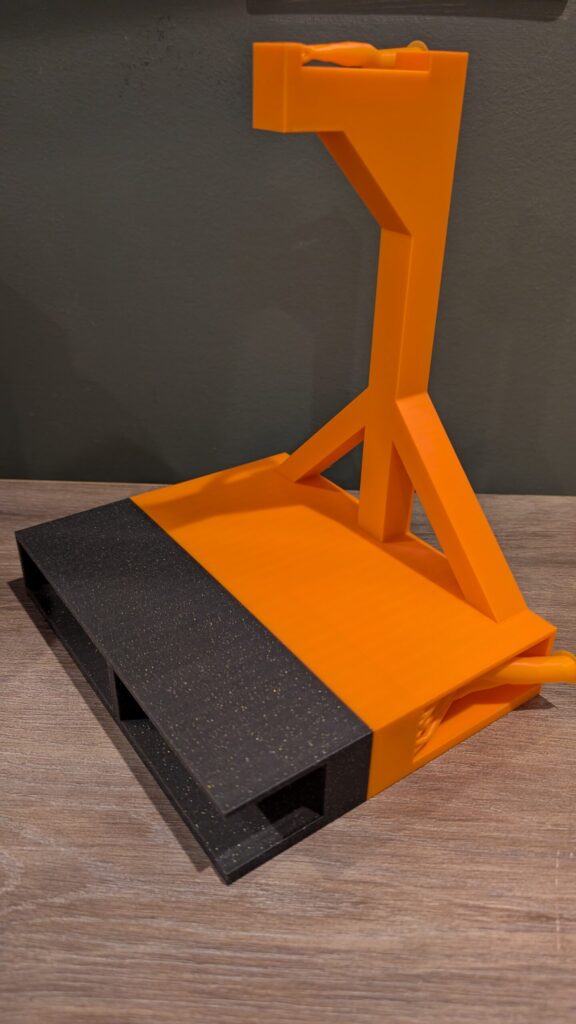
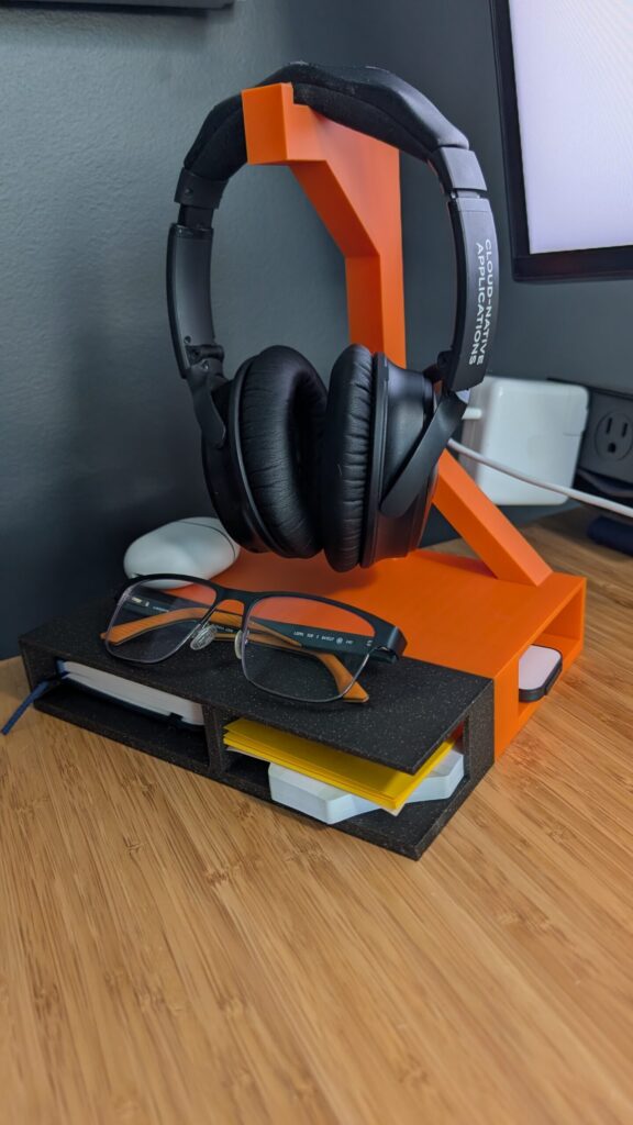
Two-tone print (I ran out of orange filament partway through, hence the color swap for the base, not a design choice, but I like how it looks). Headphones rest securely on the angled arm, compartments underneath hold glasses, a notebook, and sticky notes.
What I’d tell someone trying this themselves
- Sketch on paper first. It forces clarity before you generate anything.
- Give exact numbers, not vibes. “About 45 degrees” and “exactly 45 degrees, equal rise and run” produce very different results.
- Don’t trust a single render. Ask for the actual coordinates or a cross-section when precision matters, pictures can be visually misleading even when the underlying geometry is correct (or wrong).
- Check your units before you slice. This is the single most common way a good design becomes a garbage print.
- Expect iteration. My first version wasn’t close. My sixth version was.
If you want the CAD script or the final STL, reach out, happy to share.